Detolf lighting with WS2812 and Homeassistant
Preface
We have a few Ikea detolfs around the house and have had issues lighting them in a satisfactory manner.
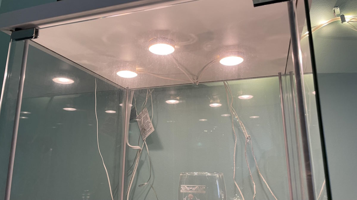
Initially I used the “stock” option of sticking 3 ledberg spotlights at the top of the case and feeding power through the lid, but this doesn’t provide even lighting through the layers, and left power leads dangling off the case.
I iterated over a few revisions which used 5v LED tape soldered to USB leads, but still had a few issues. The first pass used a zig-zag ladder pattern along the front which was good for spreading light between the layers, but was very visible and didn’t inject much more light overall. Further, the passive USB-based input was definitely not the right tool for the job once you get past about a meter of tape.
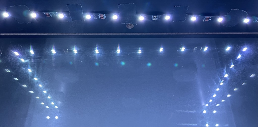
The second pass, while still passively controlled, wrapped the tape around the edges of the case which significantly increased the surface area of light emitted while also not cutting into the view of the case itself. As this introduced right-angles into the equation, the tape needed to be cut and rotated with the use of corner-addons (more on this later)


conveniently, the perimiter path is around 14 feet, putting it comfortably within the standard 5-meter LED tape size!
While working through it though I realized I wanted greater control and functionality out of the whole setup. With passive control we’re locked into a single hue and on/off functionality, but by moving to a WS8212 and smart guts, I could stick with the same form factor, but improve everything else with the power of an arduino board and home automation.
The Corners
The most involved part of this project was managing the four required 90° turns.
Initially I made use of the bulk-pack alligator clip ones, however between the inconsistent contact and greatly accelerated power loss between segments made them more trouble than they were worth.
After doing some research, I came across a great writeup by Josh Levine tackling this exact issue that set down a board design (which looks to have hit some level of indie manufacture in the time since). As you can see, we did make some slight modifications, but otherwise the design is a real winner! We opted for 3rd party fabrication rather than etching the boards in-house though as that’ll be reserved for a future project. The design itself accommodates the pixels being soldered for “left” and “right” bends, but make sure to figure out which and how many you need before soldering things down. In my case I needed 4 “left” bends as the tape progresses in a spiral pattern. Populating the pixels can either be done by cannibalizing extras from the strip or ordering extras. I went with a batch from adafruit and they’ve been great.
Power
Rule of thumb I’ve seen for WS8212B/SK6812 is to budget approximately 50mA per pixel. In this instance, a standard 30/m string for a 5m length sums up to 5v at 7.5A, so I rounded up to a 10A supply.
Be aware that with cheap power supplies, you get what you pay for. From reviews and from experience, drive the average supply anywhere near its rated amperage and voltage sags will not be far behind. This is a twin peril with the “helpful” barrel breakout jacks that may be included with the purchase.

Typically these are thrown in with the “normal” 5v-laptop-brick types of supplies, but please do yourself a favor and spend a few bucks on ones that won’t burn your house down. The high resistance (and iffy internal contacts) can wreak havoc on stability and the power spent dumping waste heat can easily eat whatever headroom is left in the power budget. Save yourself the headache and spend a few extra dollars on a purpose built socket (like this).
I’ve found that at this length of tape, powering the strip from both ends is warranted. powering from only one side will technically work, but you will see drop-off over the length of the strip.
The Code
One of the simplest portions of this whole rigamarole was integrating with Home Assistant.
Using ESPHome’s Neopixelbus platform, things went very smoothly
One element that wasn’t self-evident but turned out to be a great addition was bespoke color presets. Using an online color temperature calculator. By taking our nominal channel brightness of 255 and dividing each component into it, we get the proportion of each channel needed for a particular temperature. This means we get a stable hue with brightness control without any additional fuss.


The operative part of the codeblock is pasted below:
1 | light: |